What Does Daisy Chaining Mean for Power Supplies?

November 15, 2022
The colloquial term daisy chaining has established itself as a description for the direct connection of technical devices in series. In this blog article, you will learn what you should consider if you want to operate several power supplies in a daisy chain.
Daisy chaining refers to a wiring scheme in which several devices, such as power supplies, are connected directly in series. This type of wiring is also referred to as “looping through”. The English term “Daisy Chaining” is used colloquially, since the structure is vaguely reminiscent of a daisy chain. The principle can be used both to achieve a higher total current and to transmit analog signals or digital data.
If the wiring of a power supply system is planned according to this principle, it is not wired in a star configuration. Instead, the current is looped through to the load in a linear or ring-shaped manner on one line.
Is daisy chaining recommended for power supplies?
Before setting up a power supply system using the daisy chain method, it is essential to check the data sheet for the relevant type of power supply. Some power supplies do not allow direct connection of outputs. If this warning is ignored, there is a safety risk. It can lead to overloaded circuits and even fire hazard.
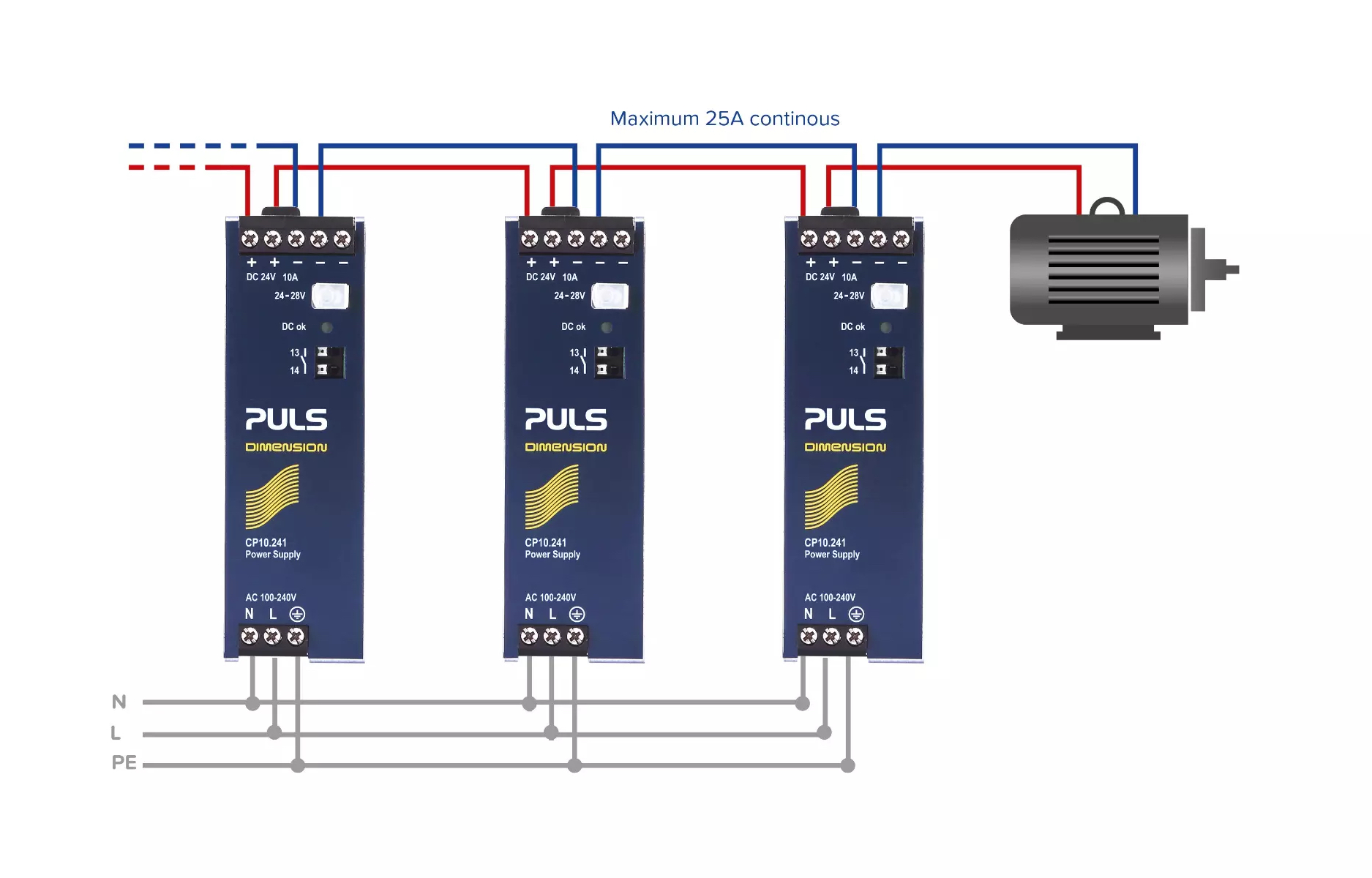
Graphic 1: With daisy chaining, the power supply outputs are directly connected to each other. It is important to have a look at the data sheet beforehand
If a power supply is suitable for daisy chaining the outputs, particular attention must be paid to the specification of the connection terminals. The decisive factor here is the load on the terminals: The maximum specified current of the terminal must not be exceeded, even with the last power supply in the series. PULS specifies the corresponding current values in the product data sheets. For example, a maximum current of 25A is permissible for the 240W power supply(24V, 10A). (See graphic 1) If more than three power supplies are connected in parallel, a fuse or circuit breaker must be integrated for each power supply output. Alternatively, a diode or acan be used. This protective measure increases the safety of the parallel connection.
Incidentally, devices with output terminals, which feature two positive poles and three negative poles, are best suited for daisy chaining. Most PULS power supplies are equipped with these terminals as standard.
As you can see, daisy chaining should only be used with caution on power supplies and by qualified staff. But what if this method is not allowed for the selected power supply according to the data sheet? Or, if it is theoretically allowed, but the required current should be higher than the specified current which is allowed for the connection terminals?
What is the alternative to daisy chaining?
A reliable alternative to daisy chaining is the usage of distribution terminals in the control cabinet. In this case, the outputs of the power supplies and the input of the load are connected to the distribution terminals. (See graphic 2) The total current is thus no longer limited by the maximum current allowed for the power supply terminals and can be higher.
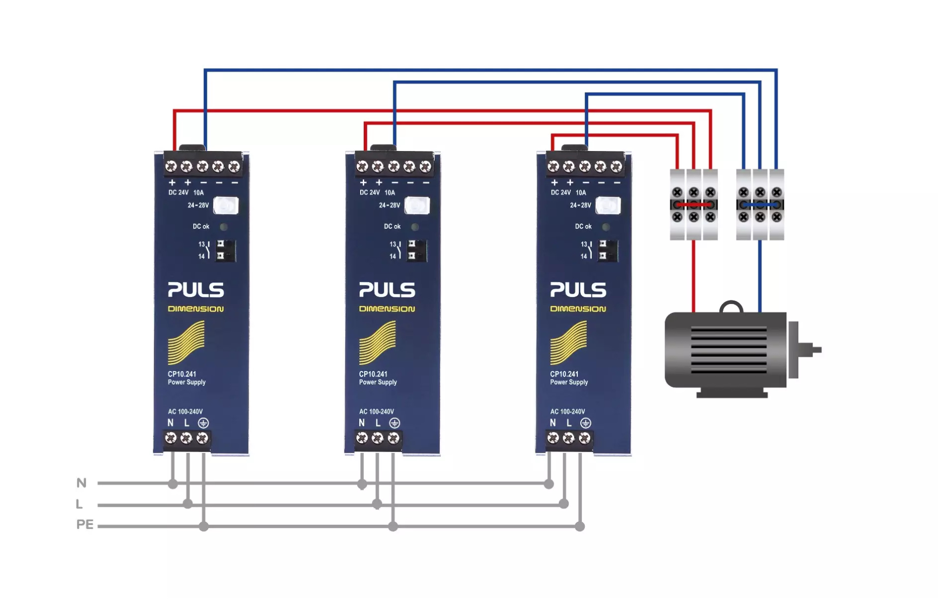
Graphic 2: The use of distribution terminals enables a higher total current
Conclusion
Daisy chaining of power supplies is a common practice in industrial applications. To increase the total current, the outputs of several power supplies as well as the load can be connected directly to each other. The decisive factor here is the information on the maximum permissible current that may flow through the connection terminals of the power supply units. These values can be found in the respective data sheet. However, not all power supplies are suitable or approved for daisy chaining. Therefore, this wiring method should always be carried out only by qualified staff on the basis of the data sheet information.
![]()